Understanding Three-Way Switch Wiring
Embark on a new experience with this guide‚ exploring the functionalities of your 3-way switch setup; a troubleshooting section is included for assistance․
This manual is your passport to possibilities‚ detailing features‚ installation‚ and operation of your new switch system‚ ensuring a seamless and informed experience;
A simple switch controls lights from one location‚ but three-way switches offer control from two points – ideal for hallways‚ staircases‚ or larger rooms․

What is a Three-Way Switch?
Unlike a standard switch that simply breaks or completes a single circuit‚ a three-way switch is designed to control a light fixture from two different locations․ This functionality is achieved through a unique internal mechanism and wiring configuration‚ differing significantly from single-pole switches․
Essentially‚ a three-way switch doesn’t have “on” and “off” positions in the traditional sense․ Instead‚ it redirects the flow of electricity along one of two “traveler” wires․ These traveler wires connect the two three-way switches‚ allowing either switch to change the state of the light – turning it on or off‚ regardless of the other switch’s position․
Key to understanding is recognizing the common terminal‚ which receives power from the source or connects to the light fixture․ The traveler terminals are interchangeable and facilitate the switching action between the two locations․ This setup provides convenience and flexibility‚ making it ideal for areas requiring control from multiple entry points․
Why Use a Three-Way Switch?
The primary benefit of employing a three-way switch lies in the enhanced convenience it offers․ Imagine entering a room and being able to turn on the light from either doorway – eliminating the need to retrace your steps․ This is particularly valuable in hallways‚ stairwells‚ and large bedrooms․
Beyond convenience‚ three-way switches contribute to increased safety and energy efficiency․ You can turn off lights from a distance‚ preventing unnecessary energy consumption and potentially deterring intruders․ This feature is especially useful in outdoor or semi-outdoor areas․
Furthermore‚ three-way switching adds a level of sophistication to your home’s electrical system․ It’s a relatively simple upgrade that significantly improves usability and demonstrates a thoughtful approach to home automation․ Ultimately‚ it’s about making your living space more comfortable and functional․
Essential Components for Wiring
Successful installation requires three-way switches‚ appropriate electrical wire (14/2 or 12/2)‚ and reliable wire connectors – often wire nuts – for secure connections․
Three-Way Switches (Traveler & Common Terminals)
Understanding the terminals on a three-way switch is crucial for correct wiring․ Unlike standard switches with just two terminals‚ three-way switches feature three: a common terminal and two traveler terminals․
The common terminal is typically darker in color and receives power from the source or sends power to the light fixture․ The traveler terminals are used to carry the electrical current between the two switches‚ enabling control from either location․
Identifying these terminals is key; often‚ they are marked or color-coded․ Correctly connecting the wires to these terminals ensures the circuit functions as intended‚ allowing you to control the light from both switch locations․ Miswiring can lead to malfunctions or safety hazards‚ so careful attention to detail is paramount․
Proper identification and connection of these terminals are fundamental to a successful three-way switch installation․
Electrical Wire (14/2 or 12/2 with Ground)
Selecting the correct electrical wire is paramount for a safe and functional three-way switch installation․ Typically‚ 14/2 or 12/2 wire with a ground is used‚ but the appropriate gauge depends on the circuit’s amperage and local electrical codes․
The “14/2” or “12/2” designation indicates the wire gauge (14 or 12 AWG) and the number of conductors – two insulated wires plus a bare ground wire․ The lower the AWG number‚ the thicker the wire‚ and the more current it can safely carry․
Always prioritize safety by adhering to local codes and using wire rated for the intended application․ The ground wire is crucial for safety‚ providing a path for fault current to return to the source‚ tripping the breaker and preventing electrical shock․ Ensure all connections are secure and properly insulated․
Choosing the right wire guarantees a reliable and safe electrical system․
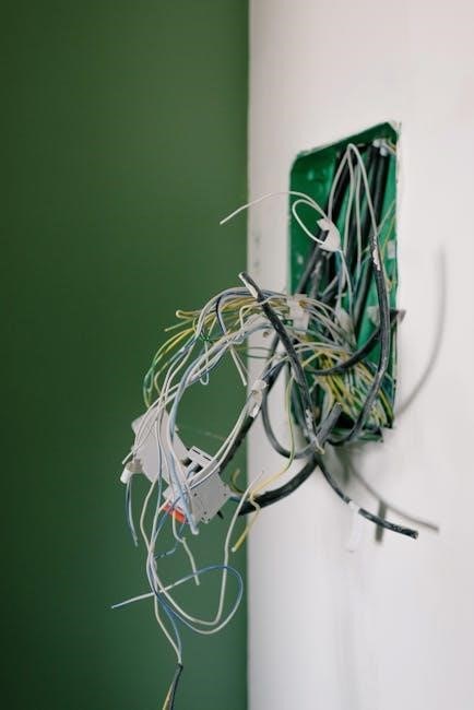
Wire Connectors (Wire Nuts)
Secure and reliable connections are vital in any electrical wiring project‚ and wire connectors‚ commonly known as wire nuts‚ are the standard method for joining wires․ These small‚ insulating caps twist onto the stripped ends of wires‚ creating a safe and permanent connection;
Wire nuts come in various sizes and colors‚ each designed to accommodate a specific number and gauge of wires․ Selecting the correct size is crucial to ensure a tight and secure connection‚ preventing loose wires and potential hazards․
When installing‚ ensure the wires are twisted together firmly before applying the wire nut‚ and twist the nut on tightly․ A gentle tug on each wire should confirm a solid connection․ Properly installed wire nuts prevent shorts‚ overheating‚ and potential fire risks;
Always inspect connections for tightness and security․

Step-by-Step Wiring Diagram (Basic Setup)
Follow a clear diagram for success! Begin by identifying wires‚ connecting power to the first switch‚ running travelers‚ and finally‚ connecting the light fixture․
Identifying the Hot‚ Neutral‚ and Ground Wires
Before commencing any wiring‚ accurately identifying the wires is paramount for safety and functionality․ The hot wire‚ typically black‚ carries the electrical current from the power source․ Use a voltage tester to confirm it’s de-energized before touching it!
The neutral wire‚ usually white‚ provides the return path for the current․ It’s crucial not to interrupt this path during installation․ Finally‚ the ground wire‚ often bare copper or green‚ is a safety feature‚ diverting fault currents to prevent shocks․
Carefully examine the cable entering the switch boxes; often‚ the hot wire is marked‚ but always verify with a tester․ Incorrectly identifying these wires can lead to short circuits‚ fire hazards‚ or non-functional switches․ Double-check your work before proceeding to the next step!
Connecting Power Source to First Switch
Begin by connecting the hot wire from the power source to the common terminal on the first three-way switch․ This terminal is usually darker in color and often marked․ Securely fasten the wire using a wire connector (wire nut)‚ ensuring a tight connection․
The neutral wires from the power source should be connected directly to the neutral wires heading towards the light fixture‚ bypassing the switch entirely․ Similarly‚ connect the ground wire from the power source to the ground wire in the box and to the grounding screw on the switch․
Double-check all connections for tightness and proper insulation․ A loose connection can cause arcing and potential fire hazards․ Remember to turn off the power at the breaker before and during this process for utmost safety․
Running Traveler Wires Between Switches
Utilize a 14/2 or 12/2 cable (with ground) to run the traveler wires between the two three-way switches․ These wires are crucial for enabling control from both locations․ Connect the two traveler wires to the remaining two terminals on each switch – these are typically lighter in color․
It doesn’t matter which traveler wire connects to which terminal on either switch; the functionality will remain the same․ Securely fasten each wire with a wire connector‚ ensuring a robust and reliable connection․ Proper insulation is key to preventing shorts․
Carefully route the cable through the wall or ceiling‚ avoiding any damage to the insulation․ Ensure the cable is securely fastened to studs or joists to prevent sagging or strain․
Connecting Light Fixture to Second Switch
At the second switch location‚ connect the neutral wire (typically white) from the power source directly to the neutral wire of the light fixture using a wire connector․ The ground wire (bare copper or green) should also be connected between the switch‚ the light fixture‚ and the electrical box for safety․
The remaining wire‚ often black‚ from the light fixture connects to the common terminal on the second three-way switch․ This terminal is usually darker in color than the traveler terminals․ Ensure a secure connection using a wire nut․
Double-check all connections before proceeding․ A loose connection can cause flickering lights or even a fire hazard․ Once verified‚ carefully tuck the wires into the electrical box and mount the switch securely․
Advanced Wiring Scenarios
Explore expanded setups‚ including wiring multiple lights controlled by a single three-way circuit‚ or integrating a dimmer switch for adjustable brightness levels․
Wiring with Multiple Lights
Expanding beyond a single fixture‚ wiring multiple lights with three-way switches requires careful planning and adherence to electrical codes․ The core principle remains the same – utilizing traveler wires to transmit the signal between switches – but the wiring configuration becomes more complex․
Typically‚ you’ll connect the light fixtures in parallel‚ ensuring each receives power simultaneously when either switch is activated․ This involves running separate wires from the common terminal of the second switch to each light fixture․ Remember to maintain consistent grounding throughout the entire circuit for safety․
Consider the load capacity of the switches and the circuit breaker․ Adding too many lights can overload the system‚ potentially causing a trip or even a fire hazard․ Consult a qualified electrician if you’re unsure about the load calculations or the wiring process․ Proper wire gauge is crucial for handling the increased current draw․
Using a Three-Way Switch with a Dimmer
Integrating a dimmer switch into a three-way circuit allows for adjustable lighting levels from both switch locations‚ enhancing ambiance and energy efficiency․ However‚ compatibility is key; standard dimmers aren’t designed for three-way applications․

You’ll need a specifically designed three-way dimmer‚ or a dimmer paired with a companion switch․ These systems utilize the traveler wires to transmit dimming signals‚ ensuring smooth and consistent control․ Wiring involves connecting the dimmer to the common terminal of one switch and the companion switch to the other․
Carefully follow the manufacturer’s instructions‚ as wiring configurations can vary between brands; Incorrect wiring can damage the dimmer or create a safety hazard․ Always test the functionality after installation‚ verifying that dimming works correctly from both switch locations․ Ensure the dimmer is compatible with the type of bulbs used․

Troubleshooting Common Issues
If the light fails to illuminate‚ or switches don’t function correctly‚ re-examine all connections for security and proper wiring‚ referencing the diagram․
Light Doesn’t Turn On
A non-illuminating light after installing a three-way switch setup often indicates a wiring issue․ First‚ re-verify the power is completely switched off at the breaker before inspecting connections․ Carefully examine each wire nut connection‚ ensuring all strands are securely fastened – loose connections are a frequent culprit․
Double-check the hot wire connection to the first switch’s common terminal and the neutral wire connection at the light fixture․ Confirm the traveler wires are correctly connected between the two switches; swapping them can disrupt functionality․ Utilize a voltage tester to confirm power reaches the first switch‚ and then proceeds through the traveler wires to the second switch․
Inspect the light bulb itself – a burned-out bulb is a simple oversight․ If all wiring appears correct and the bulb is good‚ systematically test each component to isolate the problem․ Referencing your three-way switch wiring diagram is crucial during this process‚ ensuring accurate identification of each wire’s purpose․
Switches Don’t Control the Light Correctly
Erratic light behavior – such as only working from one switch or inconsistent operation – usually points to traveler wire misconnections․ Carefully review your three-way switch wiring diagram‚ paying close attention to the traveler wire pairings between the two switches․ Swapping the traveler wires can cause unpredictable results‚ preventing proper control from both locations․
Verify the common terminals on each switch are correctly connected to the hot wire (first switch) and the light fixture wire (second switch)․ Incorrect common terminal connections will disrupt the circuit’s intended flow․ Use a voltage tester to trace the circuit‚ confirming power is reaching each switch and the light fixture as expected;
Ensure all wire nut connections are tight and secure․ Loose connections can create intermittent disruptions‚ leading to unreliable switch operation․ A systematic check‚ guided by your wiring diagram‚ will help pinpoint and resolve the issue efficiently․
Safety Precautions
Always turn off power at the breaker before starting any electrical work; use a voltage tester to confirm the circuit is de-energized for safety․
Turning Off Power at the Breaker
Prioritizing safety is paramount when working with electrical wiring․ Before commencing any work on a three-way switch‚ absolutely ensure the power supply to the circuit is completely disconnected at the main electrical panel‚ also known as the breaker box․
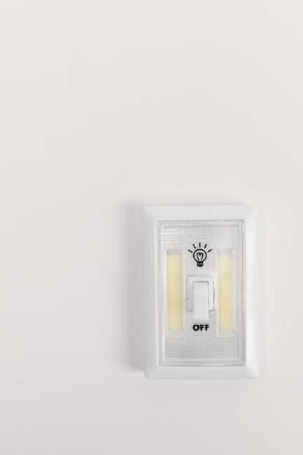
Locate the breaker that controls the specific circuit you’ll be working on – often labeled‚ but testing may be needed․ Flip the breaker to the “OFF” position․ Do not rely solely on the switch position; the breaker must be off․
Crucially‚ after switching off the breaker‚ always use a non-contact voltage tester to verify that the wires are no longer live․ Test each wire at the switch locations and the light fixture to confirm zero voltage․ This step is non-negotiable for your safety and prevents accidental electrical shock․
Remember‚ even with the breaker off‚ treat all wires as if they are energized until proven otherwise with a reliable voltage tester․
Using a Voltage Tester
A non-contact voltage tester is an indispensable tool for electrical safety‚ confirming whether a wire is live even before touching it․ These testers detect the presence of voltage through insulation‚ offering a crucial layer of protection during three-way switch wiring․
Before starting any work‚ and after switching off the corresponding breaker‚ systematically test each wire – black (hot)‚ white (neutral)‚ and bare copper (ground) – at both switch locations and the light fixture․ A beeping sound or illuminated light indicates the presence of voltage; do not proceed if voltage is detected․
Ensure the tester is functioning correctly by testing it on a known live circuit before and after verifying the breaker is off․ Replace batteries as needed․ Always follow the manufacturer’s instructions for proper usage and interpretation of results․
Remember‚ a voltage tester is a safety device‚ not a substitute for disconnecting power at the breaker․